| Projects/ Energetic industry
Automated control system reconstruction of steam generating units in station №11
Automated control system reconstruction of steam generating units in station №11
Customer : AES Ust-Kamenogorsk HPP, Ust-Kamenogorsk.
Automation object description
At Ust-Kamenogorsk HPP steam generating unit № 11 is БКЗ-320-14 -Ф2 of Barnaul Boiling Plant is applied. The steam generating units are vertical water-tube with natural circulation, single drum, and large-grained construction and of П-like assembling. The steam generating unit is to operate with the following parameters:
• productivity 320 ton per hour;
• superheated steam pressure behind steam valve -140 at;
• superheated steam temperature - 555 ºС± 2ºС.
Automation system purpose
The main purpose of the automated control system of the steam generating unit is to control the technological process of burning oil to get heat energy. The automated control system is to provide effective control of the technological process with the usage of programmed automatic regulators and carries out the functions of automatic emergency protection system. The new automated control system was elaborated instead of the old one.
The main automated control system functions are:
- automatic keeping the level in the drum;
- automatic regulation of heat load;
- automatic regulation of the superheated steam temperature;
- automatic combustion chamber draft stabilization;
- automatic control of air feeding into the furnace;
- automatic control of continuous blowdown discharge;
- automatic coal-pulverization system start and stop ;
- emergency protection ;
- technological information display as symbolic circuits with different refinement degree;
- long-term technological process variables storing;
- signaling and registration the messages of exceeding the emergency, warning and technological limits;
- system operability diagnosing;
- report making;
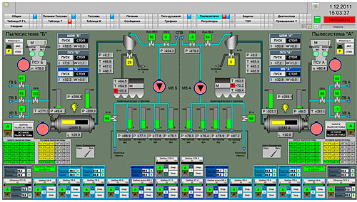
Symbolic circuits : coal-pulverization systems
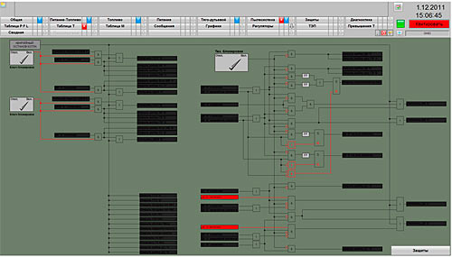
Symbolic circuits: blocking
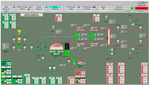
Symbolic circuits: feeding

Adjusting symbolic circuit of furnace vacuum controller
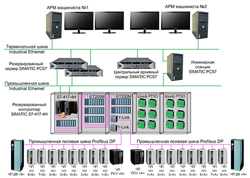
The system structure
The lower level of the system is designed on the base of reserved controller S7-417-4H with input/ output stations ET200M, that collect and process the technological parameters and control actuators. Input/ output stations ET200M are performed with the function of “emergency replacement”, i.e. have a possibility to replace the functional modules without switching off the controller and interrupting the technological process. The communication between the controller and input/ output stations ET200M is carried out via the reserved network PROFIBUS DP. The communication with the frequency converters of spray feeders, air fans and coal-pulverizer feeders is carried out via PROFIBUS DP.
The upper level of the system is a reserved server PCS7 OS Server that has as clients connected an operator’s workstation №1, an operator’s workstation №2. Each of the workstations is supplied with two displays with 23’’ diagonal.
To provide long-term data restoration the Central restoration server is used.
Software elaboration and technical support of the project is carried out from the station of the automated control system.
Data transmission between controller S7-400H and the data base server is carried out via Industrial Ethernet “electrical ring” with the carrying capacity up to 100 Mb/sec. The communication between the workstations and data base server is carried out via terminal net
Industrial Ethernet.
Symbolic circuit
The system was put into operation in 2011 |