| Projects/ Energetic industry
Automation control system of recycling water supply
Customer «AES Ust-Kamenogorsk HPP» ltd., Ust-Kamenogorsk
Automation object description
Automation object is the recycling technical water supply of HPP which is used for giving cooling water into the condensers of the turbines and air-coolers in the turbine-type generators, the later following cooling of water in the water cooling tower and repeated giving of this water by means of recycling pumps to the equipment cooled. The sectional ventilator-type water cooling tower is a part of the system as well as recycling pump station, two pressure conduits which are used for the heated cooling water to go back to the water cooling tower where it is cooled. There is also special equipment for water supply from the Ulba River to compensate the losses because of vaporizing, a droplet entrainment and a blowdown demineralizer, and the system to clean storm flows which are for the system as adding of water.
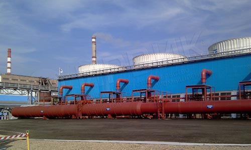
Ventilator-type water cooling tower
Automation system purpose
The main automation system purpose is to control the technical process of cooling the water circulating and the second giving of it to the condensers of the turbines
The main automated control system functions are:
- Adding water to the recycling technical water supply from the Ulba and keeping the level in the areaway of the recycling pump station;
- Keeping the temperature of the recycling water in the pool of the the water cooling tower ;
- automatic load transfer of recycling pump station;
- accident-prevention and blocking protection;
- technological information display as symbolic circuits with different refinement degree;
- signaling and registration the messages of exceeding the emergency, warning and technological limits;
- technological data and parameters, system messages long-term archiving;
- data transporting to the technological net of «AES Ust-Kamenogorsk HPP» ltd.;
- system operability diagnosing.
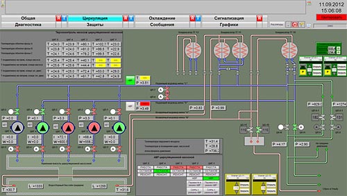
Symbolic circuit: Circulation
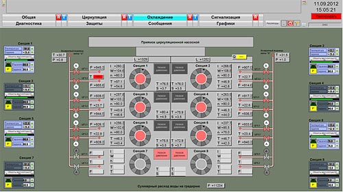
Symbolic circuit: Cooling
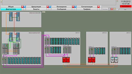
Symbolic circuit: diagnosing
The system structure
The lower level of the system for each of the units is designed on the base of reserved controller S7-414-4H with input/output stations ET200M, that collect and process the technological parameters and control actuators. Input/ output stations ET200M are performed with the function of “emergency replacement”, i.e. have a possibility to replace the functional modules without switching off the controller and interrupting the technological process. The communication between the controller and input/ output stations ET200M is carried out via the reserved network PROFIBUS DP. The communication with the remote input/ output stations ET200M is carried out via the fiber-optic network PROFIBUS DP. Network topology is dual ring. Converting of electrical signal into optic is carried out by means of optic modules of the connection OLM.
The communication with the frequency converters of ventilators motor is carried out via the reserved network PROFIBUS DP.
The upper level of the system is a reserved operator’s station PCS7 OS Single Station Redundancy . Each of the workstations is supplied with one display with 21’’ diagonal.
Data exchange between the controller S7-400H and the operator’s station is performed via the Industrial Ethernet with the carrying capacity 100 megabit/s. Due to remote location of the operator’s station from the control panel where there is a controller, data exchange is performed via fiber optic net. Network topology is the ring organized by the commutators MOXA EDS-405A. Data transporting to the technological net of «AES Ust-Kamenogorsk HPP» ltd.is carried out by means of OPC technology.
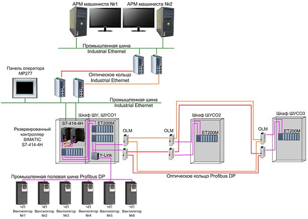
Complex Technical Means Structure Scheme
The time of the project realization
Elaboration : February – April 2012
Delivery of cubicles and controlling equipment and software – May 2012
Putting into operation – autumn 2012
|