|
Projects/ Energetic industry
Reconstruction Workflow Automated Control System of Steam Generating Unit №12
Customer: JSC «AES Ust Kamenogorsk Heat and Power Plant», Ust Kamenogorsk
Automation Object Description
Steam generating unit №12, at Ust Kamenogorsk Heat and Power Plant is the steam boiler БКЗ-320-14-Ф2 of Barnaul Boiler Plant.The boiler is a vertical water-tube boiler having gravity circulation, monocylindric, of large-block construction and it has П-like assembling.
The steam generating unit operates in the following parameters:
- productivity - 320 t/h;
- superheated steam pressure behind the steam valve is 140At;
- superheated steam temperature Тshs=555?С± 2 ?С;.
- feedwater temperature is 230?C;
- boiler water region is 83,6м 3 ;
- boiler drum preassure is 158 At;
- boiler steam region is 48,2м3.
The fire-chamber is situated in the 1st upflow flue, the water economizer and the air heater performed as the additional units in the pipe are in the second downflow flue.
The boiler superheater is radiant, of convection type, two-flow, is performed out of four grades , the total heating surface 3542 m2 .
The steam generating unit is provided with two pulverized-coal systems. Fuel drying and pulverization is performed in the ball pulverizer mills ШБМ-287/470 at speed of rotation 19 rpm. The electromotor АЗ-13-52-8, 500 kilowatt, 6000 V, rotation speed 735 rpm.
The forced-draft fans include two double-sided aspiration smoke exhausters of Д-20*2 type with the electromotor АЗ-13-52-10, 400 kilowatt, 580 rpm and two blower fans ВДН-18*2 with the electromotors 250 kilowatt, 970 rpm.
Automation system requirements
The steam generating unit is a dangerous technological object and it consists of different technological units having their own degrees of automation and requiring concerted operation.
The automation system performs the following functions;
- technological data collecting and processing ;
- the data presented as tables, diagrams and symbolic circiuts;
- technological data, warning and emergency signals, system messages archiving;
- remote and automatic control of the manufacturing equipment;
- technological parameters control and elaborating the signaling system in case the parameter exceeding the control bounds;
- disaster protection and technological deadlocks.
The automation system includes the following control loops:
- Automatic control of the boiler feedwater.
- Automatic control of the heat load regulation of the boiler.
- Automatic control of the boiler forced-draft mode.
- Automatic control of the superheated steam temperature.
- Automatic start and breakpoint of the pulverized-coal system; meal load regulation, pulverized-coal pumping, temperature of the air-coal mixture and primary air pressure on the burners are included.
- Constant blast volume regulation.
- Regulation of the level in watering system tank.
|
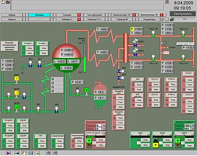
The boiler feedwater |
|
|
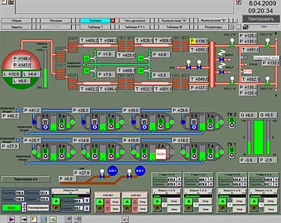
The boiler heat load and superheating |
|
|
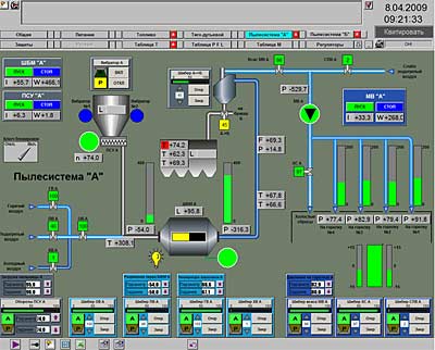
Pulverized-coal system |
|
|
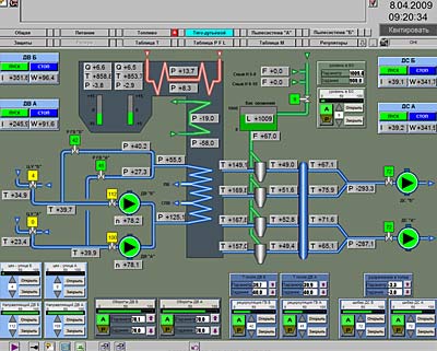
The boiler forced-draft mode
|
The system structure
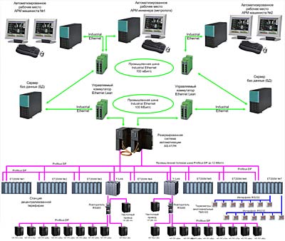
The lower level of the system is designed on the base of the redundant controller S7-417-4H with input –output stations ET200M, which collect and process the technological parameters and give the control actions on the actuating mechanisms. The input-output stations ET200M are supplied with the functions of hot swapping, i.e let substitute functional units without switching off the controller and breaking off the workflow.
The connection between the controller and the input-output stations ET200M is performed via PROFIBUS DP. The connection with the pulverized coal feeder frequency converters, the forced-draft fans and the raw-coal feeders is performed via PROFIBUS DP.
The upper level of the system is the redundant database server PCS7 OS Server v7.0, and its clients are operator’s workstation №1, operator’s workstation №2 and an engineer’s workstation. Each of them is equipped with two monitors 19 inches.
Data exchange between the controller S7-400H and the database server is performed via the redundant Industrial Ethernet «electric ring» with the carrying capacity 100 Мбит/с. The connection between the workstations and the database server is performed via Ethernet.
|
Complex Technical Means Structure Scheme |
The time of the project realization
It was put into operation in the year 2008
|